Services
1. Prototype development
This is the critical phase that includes design calculations of the included components. Gears and bearings are life rated per international standards and a preliminary layout developed to allow presentation of results and a design review session with our client. With the review completed, additional detailed design elements such as tooth modifications and additional FEA to validate the preliminary design and simulation of gear mesh detail.
2. Complete models and manufacturing drawings
With design data completed, we develop component details leading to the final assembly drawing or provide the data for the client to update their product files. This work is typically modeled in SolidWorks. The final design review is scheduled to discuss the details and to define prototype plans and the test requirements. A final report provides the design details and analysis, for the record, going forward.
3. Conceptual design feasibility
This process includes design options for client assessment and may include helpful data such as total mass and the general size along with a report to assist in client selection of which option to develop.
4. Complete models and manufacturing drawings
With design data completed, we develop component details and subassemblies leading to the final assembly drawing. This work is typically modeled in SolidWorks. The final design review is scheduled to discuss the details and to define prototype plans and the test requirements. The final design review is scheduled to discuss the details and to define prototype plans and the test requirements. A final report provides the design details and analysis, for the record going forward.
5. Testing and approval
Participate in testing as required. This may include recommendations for a test facility, tooling, and procedures. Provide onsite visit if required. Review test results and compare them to the predictions developed in design and simulation. With all this complete, head on to production. Powertrain engineers can provide vendor contacts if required.
6. The production process
Powertrain Engineers remains on board to provide answers for manufacturing questions or manage any component deviation requests.
Delivering Excellence in Every Project!
1. Project
Project typically begins with client’s definition of the loading detail, expected life, and the available interface configuration. Loading can be complex, with virtually no limit on variable load profiles.
The gears and bearings are life rated per international standards and a preliminary layout developed to allow presentation of results and a design review session with our client. With the review completed, additional detailed design elements such as tooth modifications and additional FEA to validate the preliminary design and simulation of gear mesh detail along with lubrication and cooling predictions are completed.
2. Prototype development
Provide procurement specifications if required and assist with procurement as needed. As prototype components are completed, review gear QA reports, casting results or other items upon agreement with client. Provide any assembly or tool design if required.
3. Prototype development
We provide procurement specifications if required and assist with procurement as needed. As prototype components are completed, we review gear QA reports on items upon agreement with client. Provide any assembly or tool design if so required.
4. Testing and approval
Powertrain Engineers can participate in testing as required. This may include recommendations for a test facility, tooling and procedures. We provide onsite visit if required. Review test results and compare them to the predictions developed in design and simulation. With all this complete, head on to production. Powertrain engineers can provide gear vendor contacts if required.
Geartrain design applied to client’s product
3D Mesh analysis
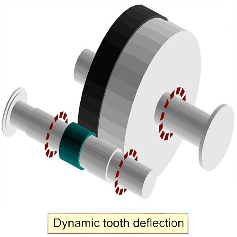
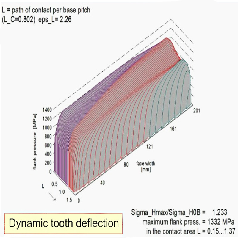
Powertrain Engineers has the software and extensive experience in what is referred to as “3D Mesh Analysis”. This includes the fine detail of the mesh as it rotates with changing stiffness, but also the influences of the gear body, pinion shaft, system bearings and housing deflections at varying load levels.This work has changed the failure rate of many customers’ products, from wind turbines to giant robot body drives to frack pumps.

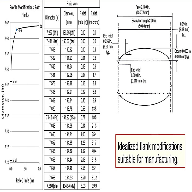
With deflections known, the tooth modifications that result in least transmission error are computed with Internationally accepted methods to apply to manufacturing drawings.
Failure analysis
1. Review available data, loads, failed components, and frequency
The intent is to understand the failure source which could be loading, design capacity product quality including material and metallurgical quality vs. the design assumptions regarding these values. It is often necessary to have failed samples to evaluate the mechanical quality and metallurgical factors of ‘real’ parts.
2. Compare failed component to design expectations
Review the measured product quality and metallurgical properties tied to the rating system variables to define the expected life based on known product properties. Compare this to the known performance to present report on life risk per the presented data and access the next steps. Prepare a detailed report of these findings and schedule a face-to-face or virtual meeting to discuss next steps.
3. Propose solution and likely change in failure rate per application
Prepare report with required changes in the design itself or the control of product quality performance or both. After design review with the client, prepare plan and cost quote to make the necessary changes in design or quality oversight to solve the product under performance.
4. Create design to achieve life targets
This activity is similar to design for client’s product except greater constraint to keep changes minimized. The gears and bearings if necessary, are life rated per international standards and a preliminary layout developed to allow presentation of results and a design review session with our client. With the review completed, additional detailed design elements such as tooth modifications and additional FEA to validate the preliminary design and simulation of gear mesh detail are completed.
5. Complete models and manufacturing drawings
With the design data completed, we develop component details leading to the final product changes allowing the client to update their product files. This work is typically modeled in SolidWorks. The final design review is scheduled to discuss the details and to define prototype plans and the test requirements.
6. Testing and approval of changes
Powertrain Engineers can participate in testing as required. As this is for an existing design, it is likely the client has the ability to test, or we can define the requirement and provide whatever additional services are required to prove the effectiveness of the proposed changes.
7. The production process
Powertrain Engineers remain on board to provide answers for manufacturing questions or handle any component deviation requests.


